

This article is about connecting the model railway with computer program RocRail and how to the first set up this program. For connecting between model railway and computer is used digital command station TCS.
What will we need?
For the simple example, we won’t need neither whole model railway, but it will be enough only the straight track divided into three separate sections. Next, we will need one digital locomotive and feedback detector (I used feedback detector with S88 bus from DCCdoma – picture 2). All of this we will connect with the command station, which supporting LAN or USB communication. I used my digital command station TCS (picture 3), which supporting two LAN protocols (Z21 and XpressNet Li-ETH). Better for use is XpressNet Li-LAN and this guide includes guide only for this XpressNet Li-ETH protocol. Everything, what will we need, is on the picture 1.

Picture 1: Everything, what will we need (Locomotive, track, command station TCS, feedback detector and computer).

Picture 2: Feedback detector with S88 bus interface fro DCCdoma.
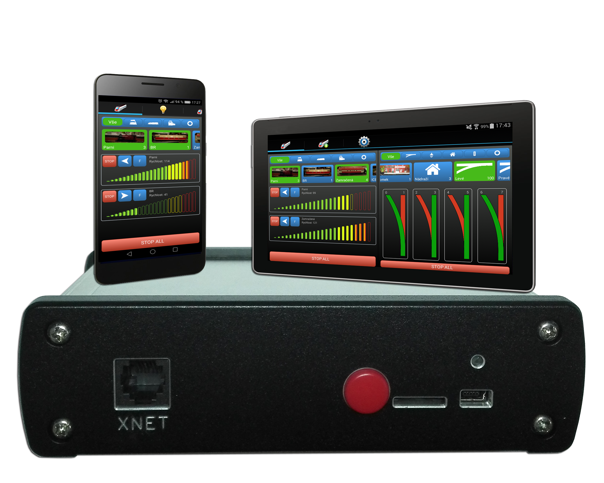
Picture 3: Digital command station TCS.
Of course, we need the computer with RocRail program.
Download and installation of the RocRail
Computer program RocRail is a free for download on the official web page, where is the documentation, too. I downloaded distribution for OS Windows and therefore all the examples will be only in OS Windows.
The first start
After we download the program and we installed it, we will launch the program. The launching of this program is not usual, we will need launch two exe files. The first is the server file rocrail.exe (picture 4) and second one is the file rocview.exe (picture 5) with graphical user interface (GUI). These steps for run the RocRail is neccessary always and these steps must be always in the right order.

Picture 4: RocRail server window (rocrail.exe)

Picture 5: RocRail GUI window (rocview.exe)
After the first run, you can change the interface language, if you want. I changed it to Czech language :-). You can do it in the top menu View->Language->“your language”. For the apply the selected language, it is neccessary close the program (both windows) and launch again in the right order.
Connecting with the command station TCS
The physical connection between the computer and the command station is not necessary, if the computer is connected into the same network (router) as a command station. Connection can be over cable or Wi-Fi. After that, we need know the IP address of the command station, which we discover in official Android application for TCS command station (after start of the application, we can see the IP address at the discovered command station or we can display more details by the long click on the command station).

Picture 6: Settings of the controller.
Next step is setting the connection between the program RocRail and the command station. We can do it in the top menu File->Rocrail Properties… in opened window on the tab Controller (picture 6). Now, we select protocol XpressNet in the bottom part of the window (part New) and click to button Add. The new command station is displayed on the top list and we can set more details by double clicking on it (picture 7). In detail window, the first we change the Interface ID to something normal. For example, I used XNET. After that, we should select Type, which is Li-ETH. The field Hostname is for IP address of the command station and the field Port should be set to 5550. Everything else is not necessary change and we can apply and save changes.

Picture 7: Details of the XpressNet controller
For the apply the all changes, it is again neccessary close the program (both windows) and launch again in the right order.
If everything is ok, after the program is launched, we can see the first communication between RocRail and command station. You can see the flashing status LED on the TCS command station. It means, that RocRail stopped the DCC signal on rails. This is the normal situation when the program is launched and closed.
Main control of the program
Before we start using this program, it is necessary know at least a few basic controls. The first is button for start and stop DCC signal, which is located on the top icon bar as the seventh button from the left. The button next to is for start automatic control. We woun’t need know the other controls for our examples.
In the right bottom corner are a few rectangles which is signaling the state of the program. If the DCC signal is not stopped and the automatic control is started, all of the rectangles should be green. In opposite case some rectangles can be red.
Manual control of the locomotive
For control the locomotive, it is necessary add the locomotive into the locomotive list in the program. We can do it in the top menu Tables->Locomotives… (picture 8). In the new opened window press the button New and select the tab General (picture 9). We will change the ID of the train from NEW to some own name, for example Lokomotiva. On the same tab, we can add the picture of the train and insert more details about locomotive, but this is not necessary for the control of the locomotive. On the next tab – Interface (picture 10) – we select the interface ID from the list. We should see the name of the command station, which we named XNET in steps before.
We should see the name of the command station, which we named XNET in steps before. We insert the DCC address of the locomotive into field Adress, I inserted 5. Next we select the Decoder steps. In my example it is 128. At the end we should set right Speed of the locomotive on the right part of the window. This speed is used for the automatic control in the next steps.

Picture 8: The list of locomotives

Picture 9: New locomotive – Tab General

Picture 10: New locomotive – Tab Interface
Now, we can apply the changes (button Apply) and save by button OK.
The new locomotive should be displayed in the left list of locomotives and after select the locomotive we can control it via control panel under the list (picture 11). The slider changing the speed of the locomotive, the arrows (“<<” and “>>”) determine the direction and buttons F0 – F4 controls functions of the locomotive.

Picture 11: Control the locomotive
Creating the first design layout of the model railway and setting the feedback
For creating the design layout of the model railroad we switch into design mode of the program by top menu Track plan->Edit panel. The menu of elements is displayed. Each element can be inserted into layout by drag and drop. List of used elements with explanation is in the table 1.
Table1: Explanation of the used elements for creating design layout
| |
Straight track – not special meaning |
| |
Ending track – not special meaning |
| |
Track with the sensor – The sensor is red, when is activated and it is green, when is deactivated. The sensor will be connected with the real sensor on the track. |
| |
Sensor – The sensor is red, when is activated and it is green, when is deactivated. The sensor will be connected with the real sensor on the track. |
| |
Left turnout – Control accessory turnout |
| |
Right turnout – Control accessory turnout |
| |
Block for train – It insert on the places, where can stay a train |
My finished layout is on the picture 12. The track is divided into three parts and on the ends of the track are blocks for locomotive. There are three sensors inserted outside the layout, which are connected with tracks on the layout.
The design layout will close in top menu Track plan->Operate.

Picture 12: My design layout of the model railway
Warning: Every elements on the layout should be right named (ID). I use for sensors S88-0, S88-1, S88-2 and for blocks block1 and block2.
Now, we will connect the real sensors on the tracks with sensors on the layout. The right click on the sensor, which we want connect, select Properties… and on the opened window we select tab Interface (picture 13). The first, we choose the Interface ID, which should be name of the command station, it is XNET for us and into Address field, we will put the address of the real sesnor on the S88 bus. I used the first three sensors, which is addressed as 0, 1, 2. Apply and save. Now, we can check the sensors working, we will put the locomotive on tracks (it should be DCC signal started) and we can see the sensor change color to red like a first sensor on the picture 14.

Picture 13: Settings of the sensor S88-1

Picture 14: Layout of the model railroad – first sensor activated
If we want see the real state of locomotive on the tracks (red tracks on the picture 14), then right click on the track and select Properties… (picture 15) and select right Sensor.

Picture 15: Connect the sensor with track.
Train routes and automatic control of the railway
For automatization of the model railway layout, there should be added the train routes. We can do it in top menu Tables->Routes… (picture 16). I added the train routes before, they are visible on the picture. For adding the new route, click to New and continue on the tab General (picture 17). In this tab, we change the name in the ID box and select the route in boxes From block and To block. There is a list of the created blocks, in our case there are blok1 and blok2. If we want run the locomotive in both direction, we should create two train routes for direction from blok1 to blok2 and contrariwise. Next to the select box with block is the checkbox marked + for selection of the direction of the locomotive. For one direction it will be like on the picture 17 and for the reverse direction there should be checked the plus next to the select box To block. Then we select the tab Speed (picture 18) for set the right speed on the route. I selected Mid. (middle), which is set in locomotive. Now, we will save everything by click to Apply and OK.

Picture 16: Table of the train routes.

Picture 17: New train route from blok1 to blok2.

Picture 18: Setting the right speed of the locomotive on the route.
The next step is add actions for blocks in routes. We will do it in block settings, after right click to the block and select Properties… then will appear the window and there we will switch to tab Routes (picture 19). Select the train route and set the reactions for the sensors for the block. I have set, if the train is on the middle part of my testing track section (sensor S88-1), then it is entering into block blok1 and if the train is on the first part of my testing track section (sensor S88-0), then it is inside the block blok1 and the train stops there. You can see yet the Event timer 1 with value 1500 ms, which is for delay before the train stops. In this case, the train don’t stop immediately, the train stops after 1500 ms after it arrives into section S88-0. We should set the actions for leaving block, too. We will do it after the click to all enter – (picture 20), then we will set action free for sensor S88-0. It means, that the block blok1 will be free, after the train leave the sensor S88-0.

Picture 19: Setting the train routes for the block blok1.

Picture 20: Setting releasing of the block blok1 after leaving the sensor S88-0.
For the block blok2, we are proceeding like for the block blok1, but we are using the different sesnors. The right settings for the block blok2 is on the pictures 21 and 22.
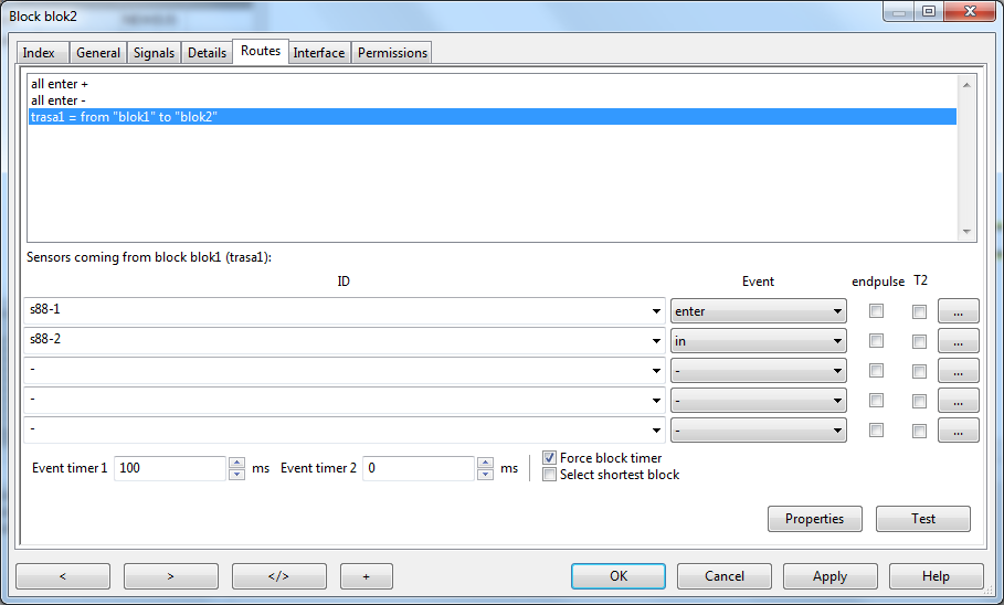
Picture 21: Setting the train routes for the block blok2.

Picture 22: Setting releasing of the block blok2 after leaving the sensor S88-0.
After everything is set, we will save all by click to Apply and OK.
Now, we can put the locomotive into the block, where it starts (e.g. blok1). We can do it by move the locomotive from teh left list into the block blok1. The locomotive name will appear in the target block and the block changes the color to red as on the picture 23. If the locomotive isn’t on the track, we can put it there and start the DCC signal output (if it isn’t yet).

Picture 23: The block blok1 is occupied by the locomotive with the name Lokomotiva.
The locomotive starts, after we will move the locomotive from the block blok1 into the block blok2. After that, the block blok2 should change the color to yellow and the locomotive should ride. When the locomotive leaves the first section, the block blok1 will be free and change the color back to white. The block blok2 change the color to blue in the same time, what indicating, that the locomotive is arriving into this block. After the locomotive arrives into the end section, this block block2 will change the color from blue to red and the locomotive stops. For more detailed control, you can watch the video on the ent of the article.
Note: You can change and combine the settings of the actions in the blocks and routes for yours model railway layout. It is only example.
Adding the control of the turnouts
This part of the article will be completed, after I will add the turnouts into my test track. We will be notified via Facebook and e-mail newsletter.
Short demonstration video
On video, you can see the demonstration, how to control the locomotive from RocRail via TCS command station with feedback detector on the S88 bus. Locomotive is Hogwarts Express from Harry Potter films in H0 (1:87).
[embedyt] https://www.youtube.com/watch?v=HqbaE1drCMY[/embedyt]
Donate money to the webpage and get more similar articles

If you want more articles like this, you can donate the money the author via PayPal or Credit card for the new modules, and other technical things. You can do it on the right column.
You can help author by sharing this article on the social networks, too.
Podobné články
 Přejděte na vyšší level a nechejte své modelové kolejiště ovládat počítač! Jak s tím začít a co všechno potřebujeme?
 DCC Command Station TCS
 The cheapest DCC sniffer with board from Arduino Nano!
 Jak přejít na digitál (DCC) [2]: Jak na výběr komponent?
 Control lights and brightness in london model house H0
 Digital control of train and turnouts on my model railroads controlled by Android application
 Bezdrátově řízený model vozidla 2
 The cheapest and fast PCB making
 Testing new features of DCC command station controlled by smartphone with Android application
Nejlevnější DCC analyzátor z Arduina Nano!
Testing new features of DCC command station controlled by smartphone with Android application
Nejlevnější DCC analyzátor z Arduina Nano!
 Choo Choo train – New model of CSD T478.1
 Model railway in Brighton Toy and Model museum in England
Pingback: Controlling Version Railway With The Aid Of A Computer – Train Model